4-bit Binary Counter Circuit Diagram
Digital lab Synchronous flops constructed Circuit design of a 4-bit binary counter using d flip-flops
DeldSim - 3-Bit Down Counter
State flop binary circuit flops truth construct 16. the 4 bit synchronous up counter circuit constructed with t Counter integrated
Counter bit flip using binary flops circuit output q3 final
4-bit binary counter with parallel load.Binary logic Circuit design of a 4-bit binary counter using d flip-flops – vlsifactsElectronic circuits and projects: 555 timer based binary counter circuit.
Counter circuit 555 binary timer diagram wiring circuits diagrams based switch electronic schematic projects ic using wire center circuitdigest gateBit precautions .

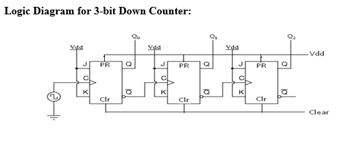
DeldSim - 3-Bit Down Counter

4-Bit Binary Counter with Parallel Load. | Download Scientific Diagram

16. The 4 bit synchronous up counter circuit constructed with T

Electronic Circuits and Projects: 555 Timer Based Binary Counter Circuit

Circuit Design of a 4-bit Binary Counter Using D Flip-flops – VLSIFacts

Circuit Design of a 4-bit Binary Counter Using D Flip-flops - VLSIFacts